

07/14/2022
![]()
Calibration of dynamic gas mixers and gas mass flow controllers in the low flow range
Dr. Frank Monshausen , QCAL Messtechnik GmbH
Many applications in the test and laboratory sector require gas mixtures with defined compositions of the components. For this purpose, dynamic gas mixers are usually used, which operate with gas flow controllers. QCAL Messtechnik uses thermal mass flow controllers (MFC) from various well-known manufacturers. These MFCs have a decisive advantage: the gas flow is independent of temperature and pressure. These MFCs are reliably calibrated, which is proven by calibration certificate provided by the manufacturer, which should be traceable to National standards. However, these calibrations are limited in two ways.
The Problem
For a limited number of gases - standard gases such as air, nitrogen, hydrogen, carbon dioxide, methane, propane, argon, helium - traceable calibrations are available. For many other gases, and especially for corrosive gases, we do not know of any calibration laboratories that can perform a DAkks calibration (or comparable). To get around this problem, many manufacturers use conversion factors or algorithms such as 'multi-gas, multi-flow ...'. However, these methods lead to unpredictable measurement uncertainties. Statements for measurement uncertainties like 'approx. 5 %' have no real background.
The second restriction refers to a limited flow range, which is often very important for the laboratory area in order to be able to produce low concentrations.
For air, the limit is 0.65 NmL/minute (NmL/minute = cm³/60s at 0°C and 1013 hPa ). For other gases such as nitrogen, carbon dioxide and others, the lower limit is even higher. As an example: a MFC that can control gas flows from 0.05 to 50 NmL/minute without extended calibration can therefore only be used in a limited control range 0.65 to 50 NmL/minute, as the range of small flows is not traceably calibrated (see Figure 1). With the extended calibration, the entire control range of the MFC can be used - shown in Figure 1 diagram between points 6 and 7 (see Figure 2).
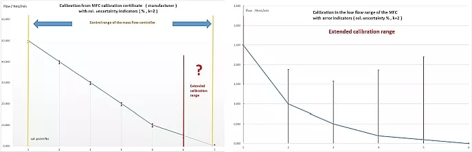
Fig.1 (left): Calibration from the manufacturer's MFC calibration certificate with indicators for a relative uncertainty
Fig.2 (right): Calibration in the lower flow range of the MFC with error displays
Two Methods for Low-Flow Calibrations
For conversions of the gas properties, the NIST software REFPROP was used. The software QMSys GUM Professional was used for the calculation of the measurement uncertainties.
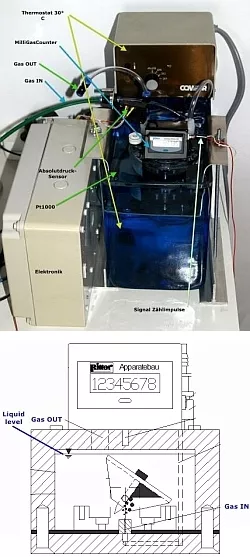
- Fig.3: MilliGasCounter with temperature
and pressure control, installed in
a thermostated circulation bath
Fig.4: Ritter Apparatebau GmbH,
functional principle
Method 1: The Milligascounter MGC
The MilliGascounter MGC (manufacturer: Ritter Apparatebau GmbH) can be used as a reference instrument for small gas flows. It can be used for gas flow calibrations from 0.017 mL/h to 17 mL/min. QCAL Messtechnik has validated this method by comparison with low-flow sensors calibrated for air according to DAkkS with a minimum flow of 0.655 NmL/min (measurement uncertainty 0.0028 NmL/min (k=2) ). The MGC has a calibrated volumetric chamber (approx. 3 cm³) inside, which is filled with the gas at a constant mass flow. When this chamber is filled with gas, the chamber is tilted and the MGC generates a signal which is recorded (N).
Because the MGC uses a volumetric measurement, it is necessary to measure the temperature T and the pressure P of the gas. The gas flow Vi(T,P) is calculated from:
With:
Vm: Volume of the measuring chamber (cm³), calibrated by the manufacturer.
N: number of tippings, source : digital counter signal output of the MGC.
t: Time difference in s , source : from microcontroller (quartz 16 MHz ).
T: Temperature (°C), source: Pt1000 temperature sensor with transducer.
P: Absolute pressure (hPa), source: pressure sensor at gas outlet
The gas flow Vi (T,P ) is converted by the REFPROP software to the normal flow at 0°C and 1013.25 hPa. All measured variables are traceable to National standards. It is very important to consider the gas solubility of the gases, therefore a suitable packing liquid must be used. We use two different MGCs, one with a water-based packing fluid, another one with SILOX (synthetic oil - polydimethylsiloxane) as packing fluid.
Before starting the measurements, the state of equilibrium - saturation and outgassing at the gas outlet - must be waited for. the achievement of this state is evident from the measurement data as shown in Figure 5. As the volume resolution of the MGC (approx. 3 cm³) is small compared to the flow rate, at least 100 tipping processes must be carried out. The mean value is calculated from these data (Figure 6). The measurement uncertainties of this method are between 4 % and 0.5 %, depending on the gas flow.
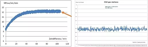
Fig.5 (left): Equilibrium state of saturation and outgassing (arrow)
Fig.6 (right): Determination of the mean value
Method 2: Low flow measurements by measuring the gas concentration of a binary gas mixture
This method requires:
- A MFC for nitrogen or air as the complementary zero gas, traceably calibrated. Gas flows from 10 NmL/minute are sufficient for this. These calibrations are available without much effort.
- A gas analyser for the admixed gas whose gas flows are to be determined. The gas analyser must have a suitable measuring range.
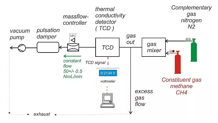
Fig.7: Example of a measurement setup: Zero gas: N2 - flow control by an MFC1 for N2, calibrated traceable to
National standards - NFlowN2 Constituent gas: CH4 - methane - flow control by a MFC2 = DUT (device under test) - NFlowDUT
The gas mixer mixes the 2 components, a binary mixture is obtained at the gas outlet.
Gas analyser: Thermal conductivity detector (TCD). The flow through the TCD is kept constant - see Figure 7 (the signal of the TCD depends on the gas flow through the TCD).
The TCD must be calibrated to CH4, for example with a calibration gas. Then the signal of the TCD can be converted into a gas concentration of CH4 in N2: CCH4, unit: Vol%.
The unknown NFlowDUT can then be calculated from:
This method can also be used if the MFC is calibrated for the constituent gas CH4 in a high flow range - but not in the low flow range. In this case, the gas analyser can be calibrated using the high-flow data. The low-flow data can be measured by changing the gas flow of the zero gas (nitrogen or air).
Example for CO2 - carbon dioxide -measured with a NDIR CO2 sensor at a concentration of 2.5 vol% CO2 in N2:
- Calibration of the sensor : the lowest flow at which the MFC2 is calibrated (NFlowDUT) for CO2 = 25 NmL/min. The MFC1 (N2) is calibrated between 10 and 1000 NmL/min. The CO2 sensor can be calibrated between 2.439 and 2.703 vol% CO2.
- Linear correction of the sensor signal output :
ConcCO2corr = Slope x Sensorout + Zero
With :
Slope = 0.98919524
Zero = 0.029840303
Coefficient of determination of the regression: 0.9999624
- A matrix is constructed for the determination of the low-flow data for MFC2. The target concentration is set to 2.5 vol% CO2. The corrected values for the standard volume flows NFlowDUTcorr are calculated from equation 2.
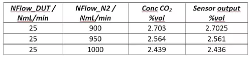
Tab.1.Calibration of the sensor
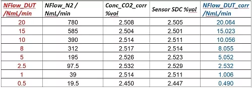
Tab.2: Calibration data from concentration measurements: Reference data (blue) and values output by the MFC (red)
With this method, a calibration table for the low gas flow range is obtained and thus extends the flow range provided by the manufacturer.